
Every successful steel project relies on two very different sets of information, yet they are often confused with one another. Design drawings set out the intent of a structure, while fabrication drawings translate that intent into precise, workshop-ready instructions. Getting the distinction right protects your programme, your budget and your reputation, which is exactly where a specialist detailing partner adds real value. At Proline Structural Detailing and Services, we bridge that gap every day, turning concept-level designs into complete fabrication packages that flow smoothly through the workshop and onto site. If you want to talk through your next job, call us on 0800 302 9982 or email jaymie.saunderson@prolinedetailing.co.uk.
Understanding where one type of drawing ends and the other begins helps you spot gaps before they become expensive problems. Below we break down what each drawing does, how they differ in practice, and why the handover between them is where most steel fabrication projects are won or lost.
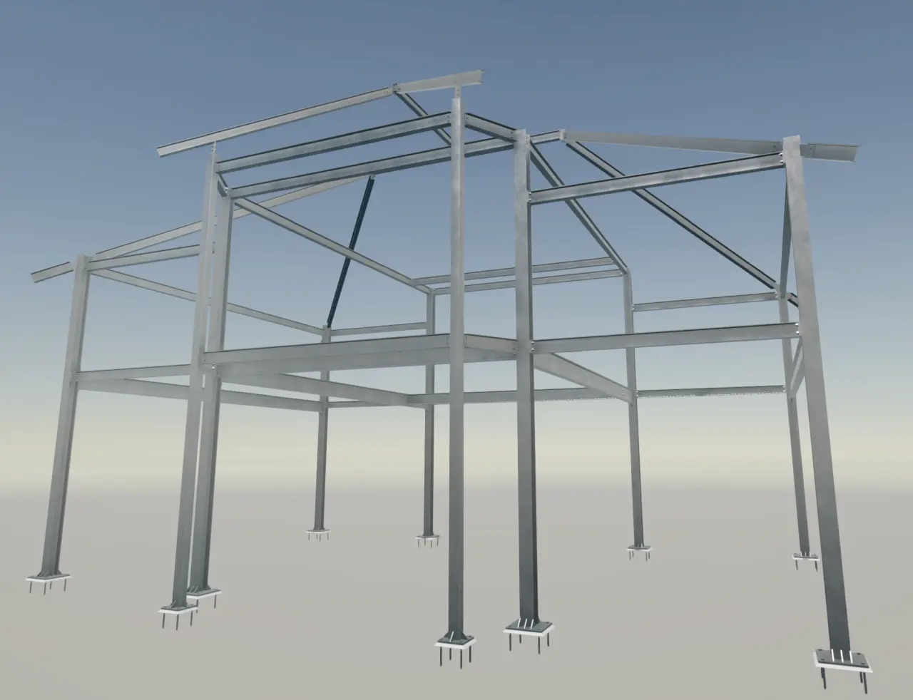
What Are Design Drawings?
Design drawings communicate the concept and engineering intent behind a structure. They are typically produced by a structural engineer or architect and answer the big questions: what is being built, where the members sit, what loads they carry, and how the frame performs as a whole.
The most familiar example is the general arrangement drawing, often shortened to GA. A general arrangement drawing shows the overall layout of the steelwork, including grid lines, member sizes, levels and key dimensions. It gives everyone involved a shared picture of the finished structure without diving into the fine detail of every cleat, bolt or weld.
A structural drawing at this stage focuses on performance and coordination rather than manufacture. It confirms that the design is sound and that the steelwork integrates with foundations, cladding, services and other trades. Design drawings are essential, but they are not enough on their own to start cutting steel. They describe the destination, not the step-by-step route to get there.
What Are Fabrication Drawings?
Fabrication drawings take the approved design intent and turn it into exact manufacturing instructions. This is the level of detail a workshop genuinely needs to produce steel accurately and efficiently.
A complete fabrication package usually includes several linked documents:
- Assembly drawings that show how individual pieces come together to form a finished unit, complete with weld details and fitting positions.
- Single part drawings that isolate every component with precise dimensions, hole positions, notches and tolerances so each piece can be cut and drilled correctly.
- Site erection drawings that guide the installation team, showing where each assembly sits and in what sequence it is craned into place.
- Bolt lists and material lists that quantify every fixing and section, supporting accurate ordering and stock control.
- CNC-ready files, such as DSTV and DXF outputs, that drive automated cutting and drilling machinery directly.
Where a design drawing might say “beam here”, a fabrication drawing specifies the exact length, the connection type, the bolt grade, the hole centres and the finish. This is the difference between a good idea and a buildable one. Our approach to structural steel detailing centres on producing these packages in a format best suited to your workshop, so nothing is lost in translation.
Design Drawings vs Fabrication Drawings: The Practical Differences
The clearest way to see the contrast is to compare the two side by side.
| Aspect | Design Drawings | Fabrication Drawings |
| Primary purpose | Communicate structural intent and layout | Provide exact manufacturing and assembly instructions |
| Typical author | Structural engineer or architect | Steel detailer using 3D modelling software |
| Level of detail | Overview and coordination | Component-level precision |
| Key examples | General arrangement drawings, structural drawings | Assembly drawings, single part drawings, site erection drawings |
| Supporting data | Loadings and specifications | Bolt lists, material lists, CNC-ready files |
| Audience | Design team and approvals | Workshop and installation teams |
| Detail depth | Moderate | Highly detailed |
Both are indispensable, and neither replaces the other. Design drawings confirm that the structure works. Fabrication drawings make sure it can be built exactly as intended, first time. The skill of good steel detailing lies in reading the design accurately and expanding it into a package that leaves no room for guesswork.
Why the Distinction Matters in Steel Fabrication
The moment a project moves from design intent to manufacture, small ambiguities become real costs. A missing dimension on a design drawing is easy to overlook until a member arrives on site too short. An unclear connection detail can halt a workshop while a query is chased down.
Accurate detailing sits precisely at this junction. By interpreting general arrangement drawings correctly and producing thorough fabrication drawings, a detailer removes ambiguity before steel is cut. This is how structural detailing improves communication between the design team, the fabricator and the site crew, keeping everyone aligned on the same information.
The knock-on effect is significant. When single part drawings are precise and bolt lists are complete, purchasing is accurate, machines run without interruption and assemblies fit together as planned. That means fewer delays, less rework and a smoother path from workshop to installation.
If your projects are stalling at the drawing stage, it may be time to bring in specialist support. You can discuss your requirements with our team on 0800 302 9982 or by emailing jaymie.saunderson@prolinedetailing.co.uk.
Common Problems Caused by Unclear or Incomplete Information
Most fabrication headaches trace back to gaps between design and manufacture. The recurring culprits include:
- Missing or conflicting dimensions, which force the workshop to stop and query, slowing the whole programme.
- Vague connection details, leaving welders and fitters to interpret intent rather than follow it.
- Incomplete material lists, leading to late orders and idle capacity.
- Uncoordinated site erection drawings, causing sequencing problems when steel reaches site.
- Non-compliant detailing that fails to meet British Standards, risking rejection at approval stage.
Each of these issues creates rework, and rework is expensive in both time and material. Reducing errors in steel fabrication with accurate detailing is not about adding more paperwork. It is about producing the right information, in the right order, so the workshop can simply get on with the job.
How Accurate Detailing Supports Approvals, Fabrication and Erection
At Proline, our process is built to catch problems early and keep projects moving. As specialists who deliver steel detailing packages across all sectors and sizes, we have refined a workflow that reflects how real workshops operate. You can read more about our background and approach on our about page.
Raising Technical Queries Early
Once a contract is agreed, we raise any technical queries that need clarifying before we proceed. Resolving uncertainty at the outset is far cheaper than discovering it mid-fabrication.
Issuing General Arrangement Drawings for Approval
We then issue a formal set of general arrangement drawings for your checking and approval. This gives you a clear opportunity to confirm the layout before we develop the detail.
Capturing Revisions
Any comments and revisions are captured and reissued, to you or to a third party where required, for final checking before release into fabrication status. Nothing progresses until the information is signed off.
Delivering the Full Fabrication Package
Once Status A approval is received, we produce your complete fabrication package. This includes assembly drawings, single part drawings, all required lists and site erection drawings, delivered in the format best suited to your setup. We use advanced 3D modelling software, including Tekla detailing, to create workshop-ready drawings and CNC-ready data that integrate seamlessly with your fabrication process.
This structured approach applies whether the job is an industrial mezzanine, a residential extension frame or a piece of bespoke architectural steel detailing. Our recent work spans walkway structures connecting storage tanks, apartment block frames coordinated to a main contractor’s erection sequence, gymnastics mezzanines, feature balustrades and new garage structures. You can browse examples on our projects page or explore the sectors we support.
The commercial benefit is straightforward. Precise detailing optimises productivity throughout the project, reduces rework, keeps the workshop running and protects your margin. Clear-as-day information is the difference between a job that drifts and one that finishes on time.
Ready to Move Your Project Forward?
If you want fabrication packages that keep your workshop productive and your projects on track, we would be glad to help. Get in touch with the Proline team through our contact page, call us on 0800 302 9982 or email jaymie.saunderson@prolinedetailing.co.uk to discuss your next job.
Frequently Asked Questions
A general arrangement drawing, or GA, shows the overall layout of a steel structure, including grid lines, member sizes, levels and principal dimensions. It provides a shared overview of the finished frame and is used for coordination and approval before detailed fabrication drawings are produced.
The terms overlap and are often used interchangeably. Fabrication drawings are a type of shop drawing focused specifically on manufacturing individual components, with exact dimensions, tolerances and connection details. In short, all fabrication drawings are shop drawings, but not every shop drawing is a fabrication drawing.
Assembly drawings show how separate components fit together to form a finished unit, including weld and fitting details. Single part drawings isolate each individual component, giving precise dimensions, hole positions and notches so every piece can be cut and drilled accurately. Together they form the core of a fabrication package.
Accurate detailing removes ambiguity before any steel is cut. Precise dimensions, complete bolt and material lists, and clear connection details prevent errors, reduce rework and keep the workshop running efficiently. It also supports British Standards compliance and a smoother site erection, protecting both your programme and your budget.