
Every successful build starts with the right drawings. Whether you are managing a steel fabrication package or coordinating a complex construction project, the documents you work from shape how smoothly everything comes together. A clear set of drawings keeps your workshop productive, your site team confident, and your costs under control. A confusing or incomplete set does the opposite, leading to delays, rework and lost profit. This guide breaks down the main types of construction drawings, explains what each one does, and shows how they fit together from initial concept to final erection.
If you want to talk through your next project, call us on 0800 302 9982 or email jaymie.saunderson@prolinedetailing.co.uk.
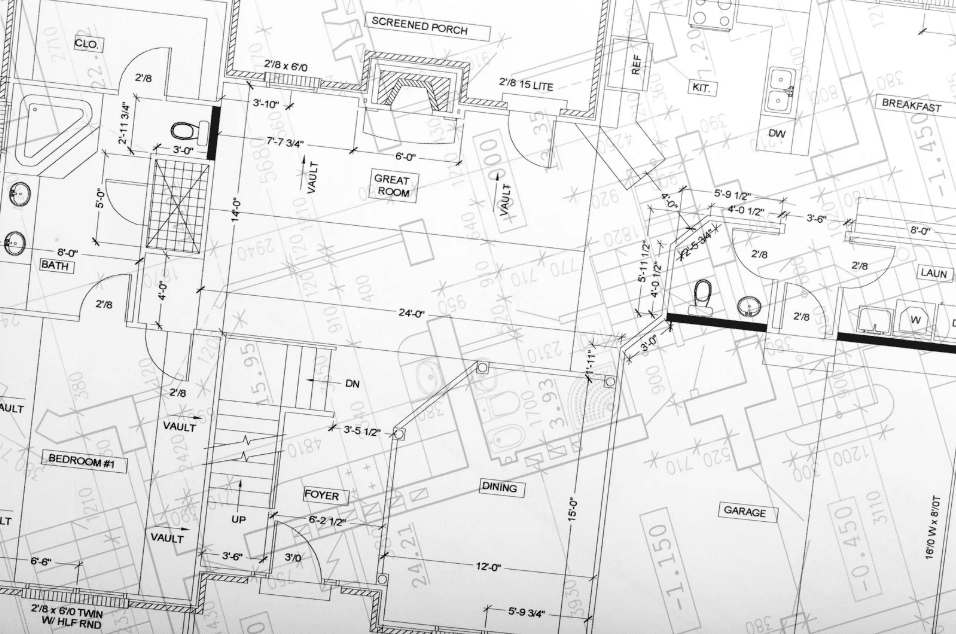
Why Construction Drawings Matter
Construction drawings are the shared language of any building project. They translate an engineer’s calculations and an architect’s vision into precise, buildable instructions. Each drawing serves a specific purpose and a specific audience, from planners and clients through to fabricators and installers on site.
Getting these documents right is not just about ticking a box. Accurate drawings reduce ambiguity, prevent expensive mistakes, and keep every trade working from the same information. When drawings are unclear or out of date, the impact ripples across the whole project: parts that do not fit, deadlines that slip, and budgets that stretch. Understanding the different drawing types helps you spot what good information looks like and where the risks lie.
The Main Categories of Construction Drawings
Construction drawings broadly fall into a handful of categories, each created at a different stage and for a different reason. Below we walk through the most common types you are likely to encounter on a steel-based project.
Architectural Drawings
Architectural drawings set the overall look, layout and function of a building. They include floor plans, elevations, sections and detail drawings that show how spaces relate to one another. These documents answer the big questions: where do walls sit, how tall is the structure, and how will people move through the finished space.
For anyone working with structural steel, architectural drawings are the starting reference. They define the aesthetic intent that the steelwork must support, whether that is an open-plan commercial floor or a feature staircase that anchors an entrance. If your project involves visible steelwork, our architectural steel detailing services show how design intent translates into precise, buildable detail.
Structural Drawings
Structural drawings focus on the elements that carry load and keep a building standing. Prepared by structural engineers, they show the size, position and capacity of beams, columns, foundations and connections. These drawings confirm that the structure can safely handle the forces acting on it, from its own weight to wind, snow and occupancy loads.
Structural drawings sit between the architect’s vision and the fabricator’s workshop. They provide the calculated framework, but they rarely contain enough detail to actually cut and assemble steel. That gap is exactly where structural steel detailing comes in, turning engineering intent into workshop-ready information.
General Arrangement (GA) Drawings
General arrangement drawings give an overall view of how the steel structure fits together. They show the layout of the frame, the positions of members, grid lines, levels and key dimensions. Think of them as the map of the project: they let everyone see the bigger picture before diving into the fine detail.
GA drawings are typically issued for review and approval before fabrication begins. They are the point where clients, engineers and detailers confirm that the proposed steelwork matches the design intent. Once these are signed off, the project can move confidently into the detailed drawing stage.
Fabrication Drawings
Fabrication drawings are where the real workshop detail lives. Sometimes called shop drawings, they provide the exact information needed to manufacture each piece of steel. This includes dimensions, hole positions, weld specifications, surface treatments and material grades. Nothing is left to interpretation.
For fabricators, the quality of these drawings directly affects productivity. Clear, accurate fabrication drawings mean parts can be cut, drilled and welded with confidence the first time. Vague or inconsistent ones create constant queries and costly delays. This is why precision at the detailing stage is so valuable, and why many businesses choose to outsource this work to specialists. You can read more about how we work to see how a structured detailing process protects your workshop’s time.
If you are weighing up your detailing options for an upcoming job, call us on 0800 302 9982 or email jaymie.saunderson@prolinedetailing.co.uk for a straightforward conversation.
Assembly Drawings
Assembly drawings show how individual pieces of steel come together to form a larger unit. They illustrate which parts weld or bolt to which, in what order, and with what fixings. Where a fabrication drawing might cover a single plate or profile, an assembly drawing shows the completed sub-section ready for delivery to site.
These drawings are essential for workshop staff who need to build complex assemblies accurately. Clear assembly information reduces guesswork on the shop floor and ensures every finished unit matches the model.
Single Part Drawings
Single part drawings strip the detail right down to one individual component. Each beam, plate, cleat or stiffener gets its own drawing showing precise measurements, hole locations and cutting requirements. These documents feed directly into cutting, drilling and profiling, often via machine-readable data.
Single part drawings are the foundation of efficient production. When they are accurate, every component arrives at assembly fitting exactly as intended, which keeps the whole sequence moving.
Erection Drawings
Erection drawings guide the team installing the steel on site. They show where each assembly goes, how the structure is built up in sequence, and how connections are made on location. Good erection drawings include marking plans, member references and clear notes that help site crews work safely and efficiently.
Because they bridge the workshop and the site, erection drawings need to be unambiguous. A confused installer is a slow and potentially unsafe one, so clarity here protects both your programme and your people.
How These Drawings Work Together
No single drawing tells the whole story. The real value comes from how they connect. Architectural and structural drawings define intent and capacity. General arrangement drawings translate that into a coordinated steel layout. Fabrication, assembly and single part drawings break that layout down into manufacturable pieces. Erection drawings then put everything back together on site.
The table below offers a quick reference to keep these roles clear.
| Drawing type | Main purpose | Primary audience |
| Architectural | Layout, appearance and function | Clients, architects |
| Structural | Load paths and member capacity | Engineers |
| General arrangement | Overall steel layout and dimensions | Detailers, engineers, clients |
| Fabrication / shop | Detail to manufacture each piece | Workshop fabricators |
| Assembly | How parts combine into units | Workshop fabricators |
| Single part | Detail for one component | CNC machines, fabricators |
| Erection | On-site installation and sequence | Site and erection teams |
When all these documents are generated from one coordinated source, the risk of contradiction drops dramatically. This is one of the biggest advantages of modern 3D modelling, where a single intelligent model produces every drawing type in alignment.
The Role of 3D Modelling and BIM Coordination
Traditional 2D workflows treat each drawing as a separate document, which means a change in one place can easily be missed elsewhere. Modern Building Information Modelling (BIM) solves this by holding all the project information in a single, data-rich 3D model. Software such as Tekla Structures lets detailers build a constructible digital twin of the steelwork, then generate GA, fabrication, assembly, single part and erection drawings automatically from that one source.
The benefits are significant. Automated clash detection identifies conflicts between steelwork and other trades before anything is cut. Changes update across the whole drawing set instantly, removing the danger of outdated information. Machine-readable data can be sent straight to CNC equipment, improving accuracy and speed. If you want a deeper look at this approach, our guide to structural steel detailing with Tekla explains the process in detail.
BIM coordination matters most on complex projects where many parties contribute. By working from a shared model, architects, engineers, fabricators and installers stay aligned, which reduces misunderstandings and keeps decisions well informed.
Common Drawing Problems and How to Avoid Them
Even experienced teams run into recurring drawing issues. Knowing the typical pitfalls helps you avoid them.
- Out-of-date revisions. Working from an old version is one of the most common causes of rework. A single coordinated model and clear revision control keep everyone on the current information.
- Missing or ambiguous detail. Gaps in fabrication or single part drawings lead to constant workshop queries. Thorough detailing closes these gaps before production starts.
- Unresolved clashes. Conflicts between steel and services discovered on site are expensive to fix. Digital clash detection catches them early.
- Poor sequencing on erection drawings. Without a clear build order, site teams lose time and safety can suffer. Logical, well-marked erection plans solve this.
The common thread is information quality. When your drawings are accurate, coordinated and clearly presented, problems shrink and your project flows. This is the standard we hold ourselves to on every package, across industrial and residential projects alike.
Bringing It All Together
Understanding the different types of construction drawings helps you recognise quality information and avoid the problems that derail projects. From architectural and structural drawings that set the intent, through general arrangement, fabrication, assembly and single part drawings, to the erection drawings that guide installation, each plays a distinct and essential role. When these documents are produced from a single coordinated model, your project gains clarity, accuracy and momentum.
If you want detailing you can rely on, backed by years of experience and a meticulous approach, we are ready to help. Call us on 0800 302 9982 or email jaymie.saunderson@prolinedetailing.co.uk to discuss your project.
Frequently Asked Questions
General arrangement drawings show the overall layout of the steel structure, including grid lines, levels and member positions. Fabrication drawings, sometimes called shop drawings, provide the detailed information needed to manufacture each individual piece, such as dimensions, hole positions and weld specifications.
Yes, the terms are often used interchangeably. Both refer to the detailed workshop drawings used to manufacture steel components. The term you hear can depend on the region and the company, but the purpose is the same.
Different drawings come from different specialists. Architects produce architectural drawings, structural engineers prepare structural drawings, and steel detailers create the general arrangement, fabrication, assembly, single part and erection drawings used to build the steelwork.
Structural steel detailing bridges the gap between engineering design and the workshop. It turns calculated structural intent into precise, buildable drawings and data, which keeps fabrication accurate, reduces rework and protects your project programme.
Yes. Using BIM software such as Tekla Structures, a detailer can build one coordinated 3D model and generate every drawing type from it. This keeps all documents aligned and removes the risk of contradictory information.